Two way long-distance card reading access controller
Product overview
Two way long-distance card reading and banning machine is a card reading and banning machine used for long-distance identification and management such as vehicle access, home school communication personnel card reading, vehicle or personnel access flow direction judgment. It is designed by combining two groups of efficient 2.4G Bluetooth card identification circuits and two-way access control circuits. It has the dual ability of card reading and access control management and the ability to judge the flow direction of entry and exit. It supports 2 sets of Wigan outputs, 2 sets of card reading enable inputs, 2 sets of door opening relay outputs and 1 set of alarm relay outputs. It adopts RS485, RS232 and TCP / IP multiple communication modes and supports the storage of 55000 user cards and 220000 records.
Product motherboard appearance introduction

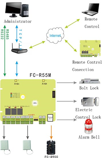
Product system structure
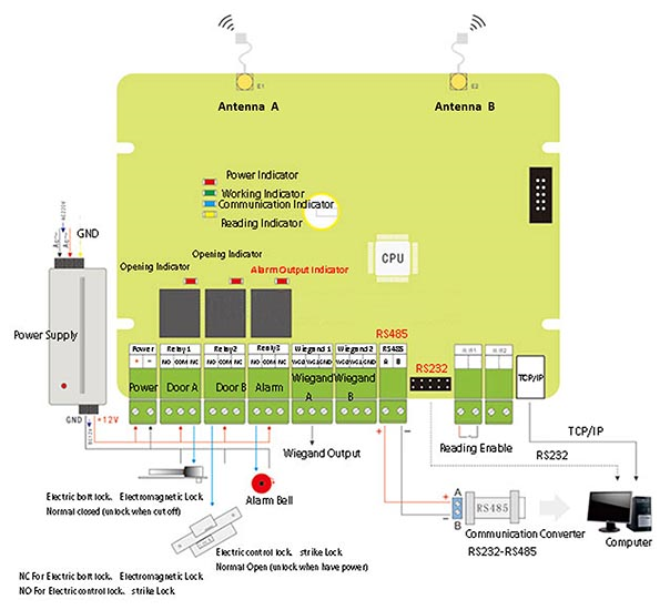
Product connection
Installation and setting of remote card reader access control machine
The automatic search device can automatically search all online access controllers, which is convenient for the device to join the system software. Click “Auto Search Access Control Equipment” in the “Install Equipment” drop-down menu of the main interface, as shown in the following figure:

Click “Auto Search Access Control Equipment” to enter as shown in the following figure:
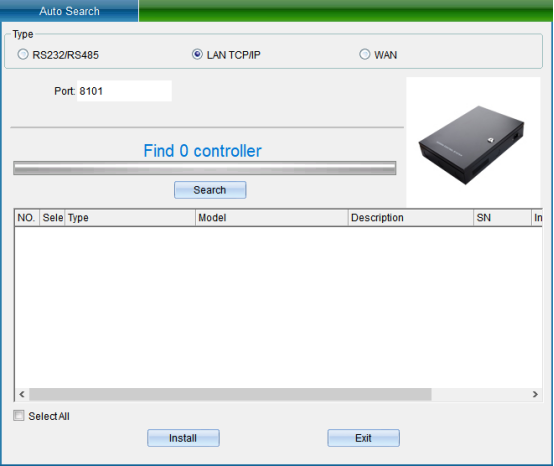
TCP/IP LAN mode: firstly, enter the network port, which is 8101 by default, and then click “Start Search”. (Note: the equipment must communicate with the computer through the switch), as shown in the following figure:
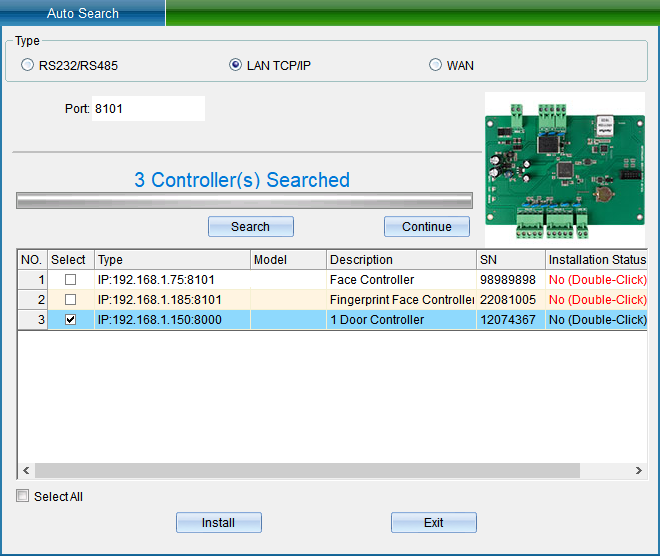
If your device is in TCP/IP communication mode, and you need to modify the device IP address (when installing the device, the user needs to check (device communication password) if the device has modified the communication password, then you need to enter the correct password to allow the modification of the IP address, so as to prevent other people from modifying the device IP through installing software, resulting in the communication failure of the original user). Then you can double-click the TCP/IP controller found to pop up the TCP connection parameter interface, as shown in the following figure:
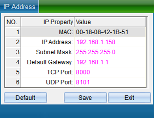
(Note: the system can search the access controller in a different network segment from the computer, but you need to modify the IP address to the same network segment address as the computer before normal communication. If the router you use supports the multi network segment mapping function, the system software can directly communicate with the access controller of other network segments.)
Double click the IP address, subnet mask and gateway address to change them into parameters matching the computer IP or LAN network segment, click “Save” to return to the installation interface, and then click “Install device” to pop up, as shown in the following figure:
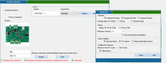
In the interface of “Install Equipment”, you can modify the name, installation position, unlocking holding time, WG byte and other settings of the access controller. If you want to modify the installation location, you can click “Select” to change it, and finally click “Save”. After saving, you can click “Access Control Equipment Management” in the “Access Control Information” drop-down menu to enter, as shown in the following figure:
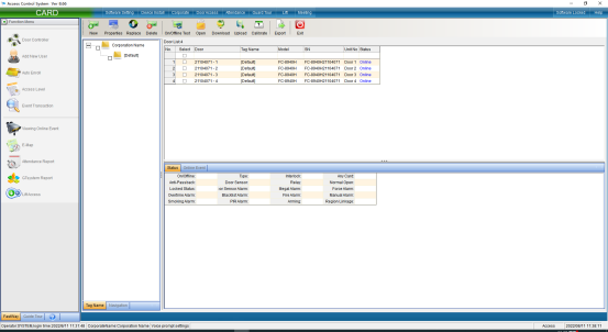
Click the “Attribute” button to pop up the interface as shown in the following figure, and select “Communication Parameters”:
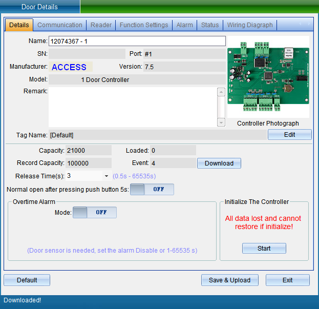
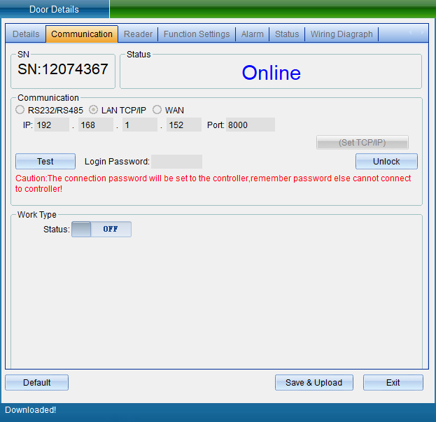
Select “Unlock Parameters” to pop up the verification password window in the figure below, enter the default password: 0000, and enter the setting of TCP connection parameters, as shown in the figure below:
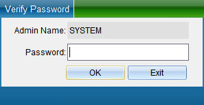

In the TCP connection parameters interface, double-click to modify the IP address. After modification, click “Save”. A window will pop up indicating success. Click “OK” to modify the IP address successfully. After modification, you need to test whether it can be connected, as shown in the following figure:
Click “Test Connection” to test. After the connection is successful, a window will pop up, and then click “OK”. If you find that the equipment time is wrong, you can click “Calibration Time” to calibrate. Click “Save” and a window will pop up indicating success. Click “OK” to finish setting parameters, and then click “Exit”.
In the communication parameter interface, you can also modify the access controller WG output type, WG byte order, access category, card number byte and other equipment parameters.
Add people and authorize
Click “Personnel File” in the drop-down menu of “Access Control Information”, as shown in the following figure:
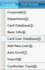
Click the “Personnel File” to enter, as shown in the following figure:
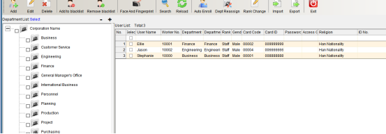
Click “Add” to enter as shown in the following figure:
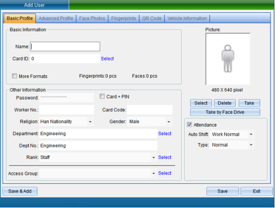
After filling in the personal information, click Save.
Click “Set Door Opening Authorization” in the “Access Control Information” drop-down menu (this function is not available in the default interface. If you want to enable more required functions, you can click “Open Function” in the “Help” drop-down menu in the upper right corner of the main interface to open more functions), as shown in the following figure:
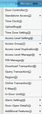
Click “Set Door Opening Authorization” to enter, as shown in the following figure:
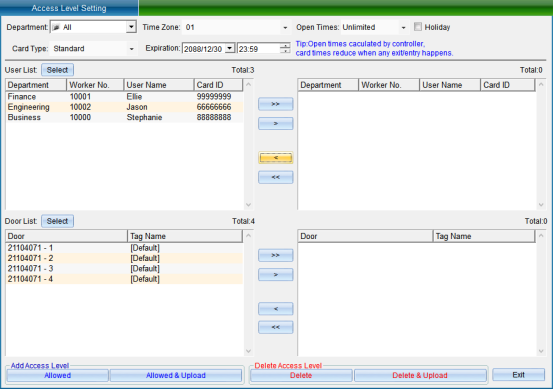
Select the person who needs to set the access control permission, select the opening period and times, the validity period, and select the equipment door. After selecting, click “allow the selected person to pass through the selected door and upload”.
[> ]: select all “Users” or all “Optional Doors”.
[>]: select a single “User” or a single “Optional Door”.
[<]: remove a single “Selected User” or a single “Selected Door”.
[< ]: remove all “Selected Users” or all “Selected Doors”.
“Prohibit the Selected Personnel from Passing through the Selected Door”: to delete the access permission of the specified user to the selected door, you must upload the settings in the synchronous data before the deletion of the permission can take effect.
[Prohibit selected personnel from passing through the selected door and uploading]: delete the user's access permission to the selected door and upload it to the controller at the same time, and there is no need to upload to the synchronization data.
[Allow selected personnel to pass through the selected door]: add the access permission of the specified user to the selected door. The added permission can only take effect after the settings are uploaded in the synchronous data.
[Allow selected personnel to pass through the selected door and upload]: add the access permission of the specified user to the selected door and upload it to the controller at the same time, without uploading to the synchronization data.
After selecting users and doors, all records can be arranged by door or by user, and you can clearly see which people are allowed to enter and exit a door and which doors a person can enter and exit.
After all permissions are set, upload the settings of the specified door to the controller.
Calibration Equipment Time
To calibrate the equipment time, click “Calibration Time” in the menu bar in the “access control equipment management” interface or click “Calibration Equipment Time” in the drop-down menu of “Access Control Information” in the main interface of the software, as shown in the following figure:
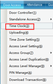
Click “Calibrate Equipment Time” to enter the interface as shown in the following figure:
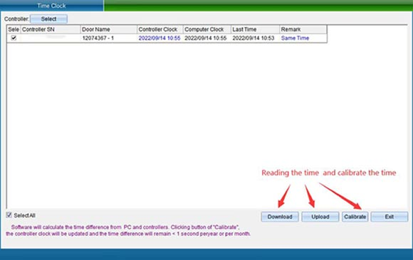
Use the clock of the computer system to calibrate the clock of the controller, so as to achieve the time synchronization between the access control intelligent management system and the controller. Please make sure whether the computer time is accurate first. Select the door you want to calibrate and click “Calibration Time”.
Upload Access Control Data
To upload data, click “Upload Data” in the “Equipment Management” interface or click “Upload Data” in the drop-down menu of “Access Control Information” in the main interface of the software, as shown in the following figure:
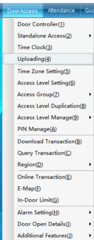
Uploading data is to upload the uploaded personnel, opening period, opening password and equipment parameters to the equipment at one time after setting them respectively. Click “Upload Data” to enter as shown in the following figure:
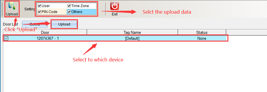
Select the content to be uploaded in the upload content, either single or all, and click “Start Uploading” after selecting the equipment. Enter as shown in the following figure:
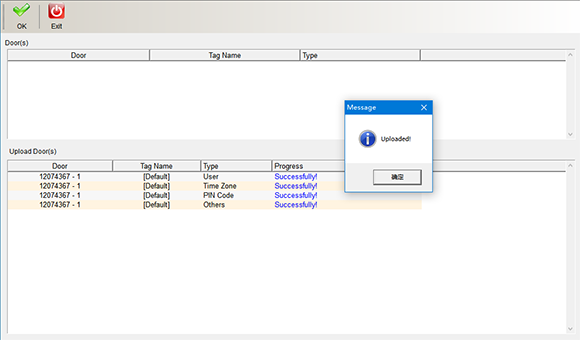
After uploading, a prompt window will pop up. Click “OK” in the window to finish uploading data. Click “Finish” and “Exit” to return to the main interface.
Copy permissions
Click “Copy Permission” in the “Access Control Information” drop-down menu, as shown in the following figure:
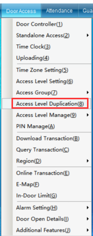
If user A has the same permissions as other users, you can copy the permissions of user a to other users through “Copy Permissions”. Click “Copy Permission” to enter the interface shown in the following figure:
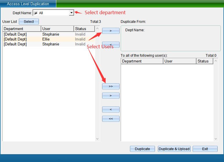
Select the personnel of a single department or all departments in the Department name, select the personnel who have the permission to open the door, and then select a single or all personnel without permission to the “copy to the following personnel” box, and then click “Copy Permission” (here, only copy the permission and not update it to the equipment) or “copy permission and download” (here, both copy the permission and update the permission to the equipment), and then click “Finish”.
Opening time management
If you want to set users' personalized permissions. For example, who can enter which doors from what time to what time, and who can enter which doors on the day of the week. Please set the “Door Opening Period” function, and multi period control can be achieved through the period. Such as special working conditions on Saturday and Sunday.
Click “Door Opening Period Management” in the drop-down menu of the software menu “Access Control Information” (this function is not available in the default interface. If you want to enable more required functions, you can click “Enable Function” in the drop-down menu of “Help” in the upper right corner of the main interface to enable more functions), as shown in the following figure:
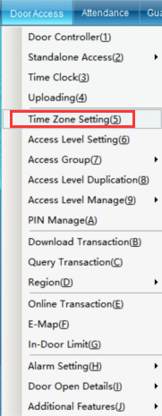
Click “Door Opening Period Management” to enter the interface shown in the following figure:
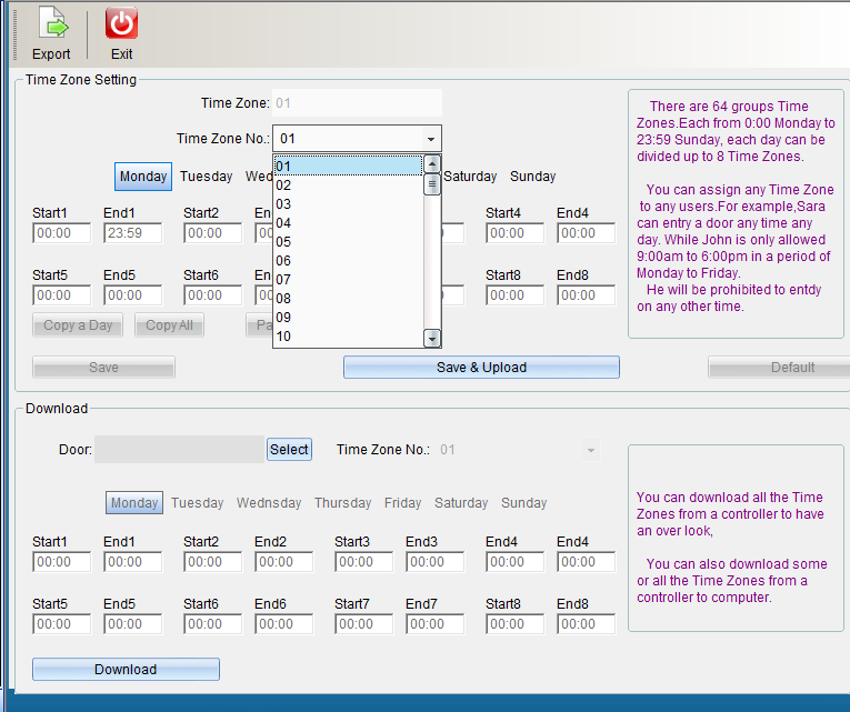
Default data: 01 group of time periods, from Monday to Sunday, are valid for 24 hours, while 02-64 group of time periods are invalid by default. To add a new opening time period, you can click opening time period 02 to start adding a time period, as shown in the following figure:
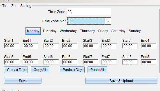
1. The name of the opening period can be changed. The opening period can be set with 8 different period limits from Monday to Sunday.
2. You can copy the set time period to the time of other weeks.
If the time is set in “Monday”, click “Copy Single Day Data”, click “Tuesday”, select “Paste Single Day Data”, and the same is true from Wednesday to Sunday. Set the completion point “Save Period Database” or click “save and upload to all access controllers”, and click “Finish” to exit after uploading the period.
If you need more than one time period, and most of the time is the same, you can copy the whole time period and paste the whole time period. If the time of time period 2 has been set and saved, you can click “copy the whole time period”, click time period 3, click “paste the whole time period” to copy the opening time of time period 2 to time period 3, and then click “save and upload to all access controllers”.
If “door opening period management” is not required, click “restore to system default”.
After setting the time period, if you need to assign a time period to the user, you need to assign the time period to the corresponding user in “Permission” before you can control the user to enter and exit the specified door in the specified time period.
Work process
Installation instructions
1. Install the antenna
Application Notes
1. Attention should be paid to lightning protection during installation.
2. The card reader access control machine should avoid working in an environment near high pressure.
3. The power supply should be regulated DC12V power supply.
4. The power supply should ensure the current of DC12V 1A or above, and ensure the power required by the card reader access control machine.
5. Similar equipment should be avoided, as similar equipment will interfere with each other.
6. The card cannot be wrapped in metal, and the metal will block the card reading.
7. The battery life of the card is determined by the card sending cycle. The longer the cycle, the longer the battery life. Please adjust the sending cycle according to actual needs.
8. In "card reading mode", no authority judgment is made, no record is generated without opening the door, and 1000 card data can be read in 1 second. (This mode is generally used in the home-school link system)
9. In "Access Control Mode", it supports permission judgment, which can judge whether the card is a legal card. Supports opening the door and saving card reading records. 1 second can handle 20 card data reading, permission judgment, door opening or alarm, record keeping, etc. (This mode is commonly used in parking lot systems)
10. RS232, RS485, WIEGAND and other communication bandwidths are small. When the card reader access control machine reads multiple cards at one time, the cards will have a process of queuing to transmit data.
11. The wiring distance of each communication interface should be carried out in strict accordance with the requirements. The TCP/IP line is within 100 meters, the RS485 line is within 1200 meters, and the RS232 line is within 10 meters.
12. The length of the AC power cord should not exceed 100 meters, and the length of the DC power cord should not exceed 20 meters.
13. When the card-reading enable interface is in a short-circuit state, card-reading is supported. When not in a short circuit state, the card is not read.
14. If you use the inflow and outflow judgment function, you should pay attention to the following issues:
1) Set the card reading mode to "pure card reading access control machine mode".
2) Use dual antennas, try to keep a distance of more than 10 meters between the two antennas to prevent signal overlap.
3) The antenna should be a directional high-gain antenna, with the two antennas facing the outgoing and incoming directions respectively.
4) Wiegand function is not supported when judging the incoming and outgoing flow.
5) Set the reading interval parameters according to the environment (requires multiple experiments to determine the appropriate value).
6) Set the card reading distance according to the environment (start the test from "close-range mode", if "close-range mode" can read all the cards in and out, you can use "close-range mode", no need to use "middle distance mode").
7) It should be ensured that the card battery and card reading performance are in the best state. If the card is often not read due to battery or other reasons, the battery should be replaced or the card should be replaced.
8) There cannot be two card-reading access control machines in a card-reading area. If two card-reading access control machines are required, please install them separately to avoid mutual interference.
Product lightning protection matters
1. In order to ensure the lightning protection effect, the corresponding lightning protection device can be installed on the solid core line, and the wiring and grounding work should be done according to the standard. The connection between the lightning arrester and the protection equipment should be as short as possible, and should not exceed 0.5 meters.
2. All lightning arresters must be well grounded and comply with national standards.
3. The entire wiring is shielded, and both ends of the shielded wire are grounded or buried.
4. The network cable and RJ-45 connector should use regular products, the line sequence is correct, and the connector is well made.