Introduction to remote card reader
The remote card reader is built with a set of 2.4G remote card reading functions. The identification distance can be adjusted from 0 to 50 meters. The card reading frequency (speed) and the card reading distance can be set according to needs. It supports opening the door after reading a legal card.
The remote card reader + access control system is a card reader used for remote identification management such as vehicle access, home school communication personnel card reading, vehicle or personnel access flow judgment. It is designed by an efficient 2.4G Bluetooth card identification circuit and has the card reading function. It can be used with the access controller to realize the management and access flow judgment. Support 1 group of Wigan output, 1 group of card reading enable input, and adopt RS485 communication mode.

Access Control Management
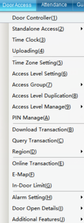
Click “Access Control Equipment Management” in the “Access Control Information” drop-down menu of the main interface, as shown in the following figure:
Click “Access Control Management” to enter, as shown in the following figure:
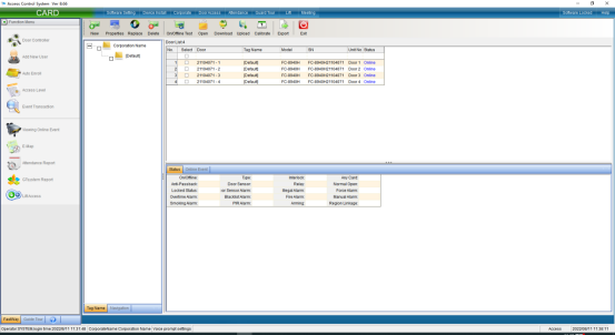
You can also add access control equipment in this interface. Click “Install”in the upper left corner to pop up the interface and install according to the prompts.
Installation and setting of access controller
The automatic search device can automatically search all online access controllers, which is convenient for the device to join the system software. Click “Auto Search Access Control Equipment” in the “Install Equipment” drop-down menu of the main interface, as shown in the following figure:

Click “Auto Search Access Control Equipment” to enter as shown in the following figure:
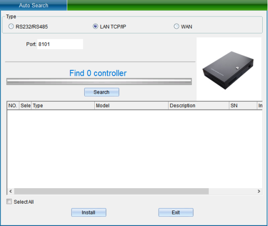
TCP/IP LAN mode: firstly, enter the network port, which is 8101 by default, and then click “Start Search”. (Note: the equipment must communicate with the computer through the switch), as shown in the following figure:
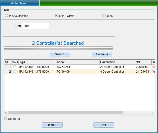
If your device is in TCP/IP communication mode, and you need to modify the device IP address (when installing the device, the user needs to check (device communication password) if the device has modified the communication password, then you need to enter the correct password to allow the modification of the IP address, so as to prevent other people from modifying the device IP through installing software, resulting in the communication failure of the original user). Then you can double-click the TCP/IP controller found to pop up the TCP connection parameter interface, as shown in the following figure:
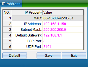
(Note: the system can search the access controller in a different network segment from the computer, but you need to modify the IP address to the same network segment address as the computer before normal communication. If the router you use supports the multi network segment mapping function, the system software can directly communicate with the access controller of other network segments.)
Double click the IP address, subnet mask and gateway address to change them into parameters matching the computer IP or LAN network segment, click “Save” to return to the installation interface, and then click “Install device” to pop up, as shown in the following figure:
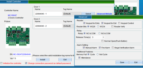
In the interface of “Install Equipment”, you can modify the name, installation position, unlocking holding time, WG byte and other settings of the access controller. If you want to modify the installation location, you can click “Select” to change it, and finally click “Save”. After saving, you can click “Access Control Equipment Management” in the “Access Control Information” drop-down menu to enter, as shown in the following figure:
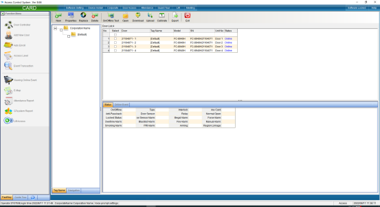
Click the “Attribute” button to pop up the interface as shown in the following figure, and select “Communication Parameters”:

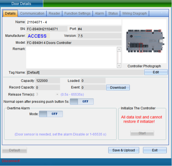
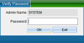
Select “Unlock Parameters” to pop up the verification password window in the figure below, enter the default password: 0000, and enter the setting of TCP connection parameters, as shown in the figure below:
In the TCP connection parameters interface, double-click to modify the IP address. After modification, click “Save”. A window will pop up indicating success. Click “OK” to modify the IP address successfully. After modification, you need to test whether it can be connected, as shown in the following figure:
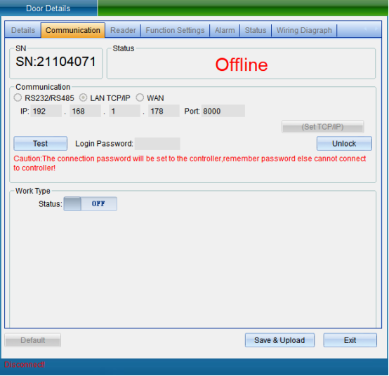
Click “Test Connection” to test. After the connection is successful, a window will pop up, and then click “OK”. If you find that the equipment time is wrong, you can click “Calibration Time” to calibrate. Click “Save” and a window will pop up indicating success. Click “OK” to finish setting parameters, and then click “Exit”.
In the communication parameter interface, you can also modify the access controller WG output type, WG byte order, access category, card number byte and other equipment parameters.
Add people and authorize
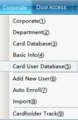
Click “Personnel File” in the drop-down menu of “Access Control Information”, as shown in the following figure:
Click the “Personnel File” to enter, as shown in the following figure:
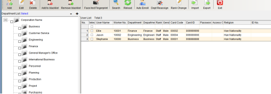
Click “Add” to enter as shown in the following figure:
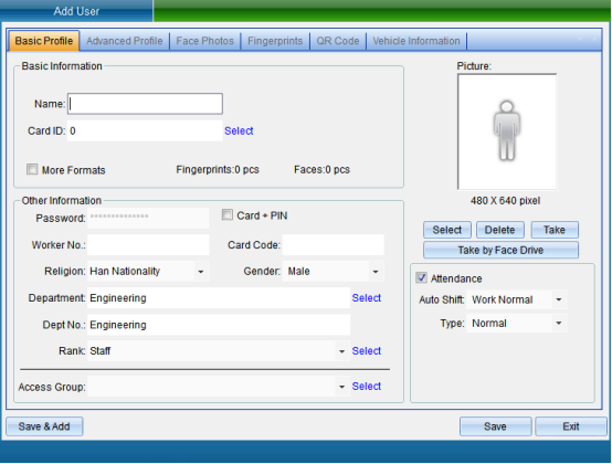
After filling in the personal information, click Save.
Click “Set Door Opening Authorization” in the “Access Control Information” drop-down menu (this function is not available in the default interface. If you want to enable more required functions, you can click “Open Function” in the “Help” drop-down menu in the upper right corner of the main interface to open more functions), as shown in the following figure:
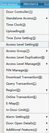
Click “Set Door Opening Authorization” to enter, as shown in the following figure:
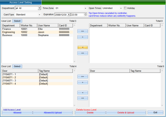
Select the person who needs to set the access control permission, select the opening period and times, the validity period, and select the equipment door. After selecting, click “allow the selected person to pass through the selected door and upload”.
[> >]: select all “Users” or all “Optional Doors”.
[>]: select a single “User” or a single “Optional Door”.
[<]: remove a single “Selected User” or a single “Selected Door”.
[< <]: remove all “Selected Users” or all “Selected Doors”.
“Prohibit the Selected Personnel from Passing through the Selected Door”: to delete the access permission of the specified user to the selected door, you must upload the settings in the synchronous data before the deletion of the permission can take effect.
[Prohibit selected personnel from passing through the selected door and uploading]: delete the user's access permission to the selected door and upload it to the controller at the same time, and there is no need to upload to the synchronization data.
[Allow selected personnel to pass through the selected door]: add the access permission of the specified user to the selected door. The added permission can only take effect after the settings are uploaded in the synchronous data.
[Allow selected personnel to pass through the selected door and upload]: add the access permission of the specified user to the selected door and upload it to the controller at the same time, without uploading to the synchronization data.
After selecting users and doors, all records can be arranged by door or by user, and you can clearly see which people are allowed to enter and exit a door and which doors a person can enter and exit.
After all permissions are set, upload the settings of the specified door to the controller.
Real-time data monitoring
Click [Real-time Data Monitoring] in the [Access Control Information] drop-down menu in the software menu bar, as shown in the following figure:
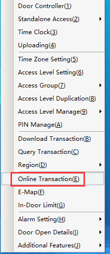
Click [Real-time data monitoring] to enter the interface as shown below:

Add the door to be monitored, click [Select Monitoring Device], and the interface as shown below will pop up:
Select the door to be monitored, and then click [Select] to automatically start real-time monitoring.
Turn on/off real-time monitoring
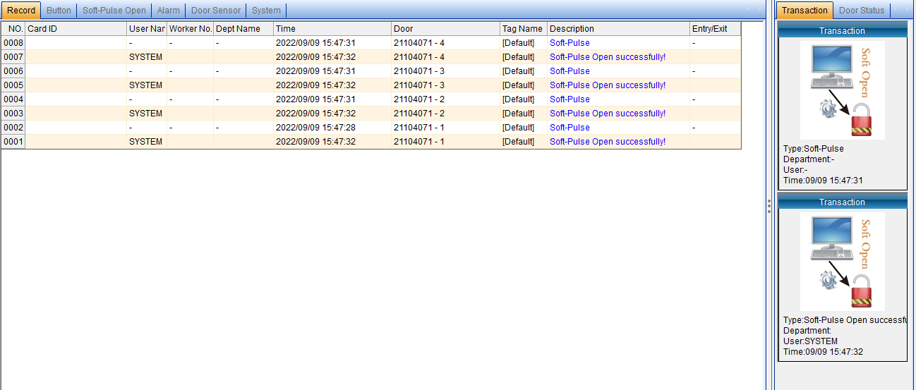
In data monitoring, when the user automatically recognizes the entry and exit of the remote card, the cardholder's "card number", "name", "department", "time", entry and exit "status" and the cardholder's "photo" can be displayed in real time. ” and other basic information. It can also monitor "exit switch", "software door opening", "alarm", "door status" and "system", as shown in the following figure:
